resources
Data Center Busway vs Rack PDU Tap-Off Checks
Verify data center busway tap-off boxes and vertical rack power distribution units across whip connections, pole and neutral bars, breaker voltage boundaries, and rack power density.
Updated October 2026
Overhead data center busway and vertical rack power distribution units divide the cabinet power feed into two distinct engineering assemblies: the overhead busbar trunking with its plug-in tap-off box above the server row, and the vertical rack power strip with its branch circuit breakers and receptacle banks inside the cabinet. According to ABB's summary of IEC 61439-6, Clause 3.110 defines a feeder BTU (busbar trunking unit) as a BTU serving as an incoming unit, and Clause 3.111 defines a tap-off unit as an outgoing unit, either fixed or removable, for tapping-off power from the BTU. In the ABB High-Density Tap-off Unit Reference Design, protection devices based on miniature circuit breakers (MCBs), molded case circuit breakers (MCCBs), or switch-fuse based technology are generally installed in tap-off boxes to feed IT racks. Inside the cabinet, on Emerson Vertiv Liebert MPH2 Rack PDUs in Section 1.3.4.1, models having more than 16-A input-current rating are equipped with UL 489-listed flush-mount rocker-style branch circuit breakers that protect each receptacle group against overload and short circuit in line-to-line, line-to-neutral, and line-to-PE conductors, and the branch circuit breaker is not designed to be used as a disconnect device for the connected load.
This engineering guide walks through the four verification checks required before releasing an overhead busway tap-off box and rack power specification for high rack power density deployments:
- Tap-off point, whip termination, and mechanical interlocks: Confirm continuous-access or spot-access tap-off seating, ground-first engagement, door interlocks, finger-safe busbar openings, and drop-cord strain relief.
- Busway pole counts, neutral bar sizing, and breaker voltage rules: Match phase, neutral, and ground bar configurations against harmonic loads and verify straight versus slash circuit breaker voltage ratings.
- Protection boundary between tap-off box and rack PDU: Separate upstream feeder and tap-off overcurrent protection from downstream rack PDU branch circuit breakers.
- High-density rack feed sizing, thermal derating, and fail-over testing: Size dual overhead feeds for continuous AI cluster loads, apply ambient temperature derating factors, and verify live redundancy fail-over.
This guide focuses strictly on the upstream boundary between the overhead busway tap-off box, input whip, and rack PDU breaker architecture. For downstream server cord selection and individual receptacle load budgeting, pair this verification with our server power cord comparison guide, our outlet count, cord gauge, and breaker audit, and our rack power selection guide for GPU servers.
Check the tap-off point, whip connection, and mechanical interlocks
The first verification step audits the physical and electrical interface where the plug-in tap-off box engages the overhead busway housing and transitions into the flexible drop whip feeding the cabinet. Overhead busway systems fall into two tap-off access architectures: continuous open-channel track busway and sandwich-style plug-in busduct. On the Starline Track Busway 1000T5 Metric System in Clause 6.1.1, the extruded aluminum housing is certified to serve as a 100% protective earth, with standard lengths of 1.5 and 3 meters (5 and 10 feet) customizable down to 3 centimeters or 1 inch, and a bottom opening that accepts plug-in units anywhere along its length and passes IEC's IP2X finger probe test. Similarly, Vertiv PowerBar Track is an open-face track busway with capacities ranging from 250 to 1000 amps rated for 100% continuous current, IP2X certified and UL 857 compliant, with extendable segments in increments from 2 to 13 feet and tap-off boxes featuring mechanical and electrical interlocks with a ground-first, break-last feature. On Vertiv PowerBar Track, tap-off box features include tap-off options up to 125A, up to 600VAC, 10KAIC and 22KAIC circuit breakers (with higher kA circuit breakers available upon request), and flush-mounted receptacles or drop cords with connectors. By contrast, Vertiv PowerBar HPB features a sandwich-style busduct with spliced joint pack, a maximum of 6 busplug outlets on a 12ft busbar length, and mechanical/electrical interlocks with a ground-first, break-last safety feature on all busplugs.

Overhead busway track above a server cabinet row with latched plug-in tap-off boxes and drop whips entering the rack tops.
When specifying or inspecting plug-in tap-off units for installation and maintenance, verify the insertion procedure, handle interlocks, and switch terminal wiring. In the Starline Track Busway 1000T5 Plug-In Insertion Instructions, installers are warned: DO NOT install Plug-in units under load; make sure breakers are in the off position. In the ABB High-Density Tap-off Unit Reference Design, a rotary handle with shaft on a tap-off box prevents opening of the tap-off box while the contacts of the breaker or the switch-fuse are in the close position. For high-amperage horizontal feeders, for Vertiv PowerBar HPB horizontal busduct applications, busplugs can be rated up to 200 kA at 600V with a mechanical interlock that does not allow the door to be opened while the busplug is in the 'on' position, and horizontal busduct must be installed with the neutral phase to the top. Inside the tap-off switch compartment, under OSHA 1910.305(c)(3)(ii), molded-case switches and circuit breakers used as switches shall be connected so that the terminals supplying the load are deenergized when the switch is in the open position.
At the certification and workplace cord level, both the overhead busway track and the flexible drop cord must meet applicable construction and strain-relief rules. The Starline Track Busway 1000T5 Metric System is ETL (US/Canada) certified to UL 857, CE and VDE certified to IEC 61439-1 (edition 2.0) and IEC 61439-6 (edition 1.0), CCC certified to GB 7251.1-2013, and NOM certified to NOM-003-SCFI-2000. On the flexible drop cord feeding the rack unit, under OSHA 1910.305(g)(2)(ii) and 1910.305(g)(2)(iii), flexible cords may be used only in continuous lengths without splice or tap, and flexible cords and cables shall be connected to devices and fittings so that strain relief prevents pull from being directly transmitted to joints or terminal screws.
| Tap-Off or Whip Checkpoint | Verified Engineering Requirement |
|---|---|
| Disconnect and socket accessibility | On Emerson Vertiv Liebert MPH2 Rack PDUs in Section 2.0, a readily-accessible input-power disconnect device must be installed near hard-wired MPH2 units, and for MPH2 units with factory-installed power cords the input-power socket or outlet must be installed near the MPH2 and must be easily accessible. |
| Hard-wired terminal gauge and torque | On hard-wired Emerson Vertiv Liebert MPH2 Rack PDUs in Table 2-1 and Table 2-2, terminal blocks for ≤32 A models accept 0.2 mm² to 6 mm² solid or 0.2 mm² to 4 mm² stranded wire (24 to 10 AWG) tightened to 0.6 Nm (4.4 lb-in.) to 0.8 Nm (7.1 lb-in.), while over 32 A models accept 0.5 mm² to 16 mm² solid or 0.5 mm² to 10 mm² stranded wire (20 to 6 AWG) tightened to 1.5 Nm (13.3 lb-in.) to 1.8 Nm (15.9 lb-in.). |
| Tap-off breaker telemetry protocols | In the ABB High-Density Tap-off Unit Reference Design, for ABB XT series breakers integrated into tap-off boxes, communication modules offer Modbus TCP, Modbus RTU, Ethernet IP, and IEC61850 directly in the breaker, while S800 breakers use SCU100 or SCU200 control units and OS switch-fuses use the ITS2 monitoring accessory via Modbus RTU. |
Verify busway pole counts, neutral sizing, and breaker voltage ratings
Once the mechanical tap-off and whip interface is confirmed, the second check aligns the internal busway conductor bars, neutral current capacity, grounding path, and circuit breaker voltage ratings with the facility power distribution architecture. Overhead busway tracks are manufactured in multiple conductor bar counts and neutral ratios to handle single-phase and three-phase loads, switched-mode power supply harmonics, and isolated grounding schemes.
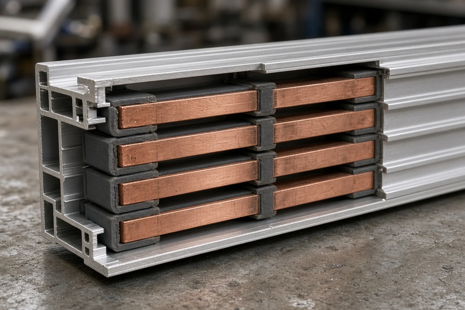
Close-up cutaway of an overhead busway extrusion showing four parallel insulated copper busbars inside the aluminum housing channel.
Across track and sandwich busway families, published specifications define exact conductor materials, neutral sizing, and short-circuit ratings. On the Starline Track Busway 1000T5 Metric System in Clause 3.1, the electrical requirements specify 415V system voltage, 50/60 Hz frequency, 51kA Icw (1 second withstand) short-circuit rating, 3 phase conductors and 1 neutral conductor of tin-plated solid copper, and earth via the aluminum casing or 1 dedicated tin-plated solid copper conductor. On Vertiv PowerBar Track, standard features include copper busway up to 600A and aluminum busway up to 1000A, up to 13 ft standard length, monitoring cable trough, up to 100 SCCR, and UL857 listing. For higher-current encased feeders, Vertiv PowerBar HPB is a 600 Volt totally encased, non-ventilated, low-impedance busduct available from 1000-4000A in Aluminum and 600-5000A in Copper. In modular high-density overhead rows, Siemens XJ-L High Density Busway offers up to twelve 100A XPM power modules installed per 10 foot of busway section, with six plug-in ports per side or twelve on one side. Furthermore, Siemens XJ-L HD Busway is 100% UL rated up to 400A at 600V max (delivering up to 288kVA at 415/240V) in 3Ø3W and 3Ø4W copper configurations with 100% or optional 200% neutral for harmonics, Std Housing (Hsg), Internal (G), or Isolated (IG) ground, and IP2X/IP40 ingress protection, and is UL 857 recognized, whereas UL 857 defines Continuous Plug-in Busway as rated at 225A or less.
Equally critical for three-phase distribution is verifying straight voltage ratings versus slash voltage ratings on the circuit breakers inside the tap-off box. Under OSHA 1910.304(f)(1)(ix), a circuit breaker with a straight voltage rating, such as 240 V or 480 V, may only be installed in a circuit in which the nominal voltage between any two conductors does not exceed the circuit breaker's voltage rating. Under OSHA 1910.304(f)(1)(ix), a circuit breaker with a slash rating, such as 120/240 V or 480Y/277 V, may only be installed where the nominal voltage of any conductor to ground does not exceed the lower value and between any two conductors does not exceed the higher value.
| Conductor or Breaker Rule | Verified Workplace Electrical Mandate |
|---|---|
| Overcurrent protection sizing | Under OSHA 1910.304(f)(1)(i), for circuits rated 600 volts nominal or less, conductors and equipment shall be protected from overcurrent in accordance with their ability to safely conduct current. |
| Grounded conductor continuity | Under OSHA 1910.304(f)(1)(ii), except for motor running overload protection, overcurrent devices may not interrupt the continuity of the grounded conductor unless all conductors of the circuit are opened simultaneously. |
| Breaker state indication | Under OSHA 1910.304(f)(1)(vi), circuit breakers shall clearly indicate whether they are in the open (off) or closed (on) position. |
Separate tap-off box overload protection from rack PDU branch breakers
The third check defines the protection boundary between the overhead busway tap-off box and the rack-mounted power distribution unit. A frequent specification error is treating the overhead tap-off box breaker and the rack PDU branch circuit breakers as interchangeable, or overlooking how internal rack PDU breaker counts limit total cabinet power capacity.
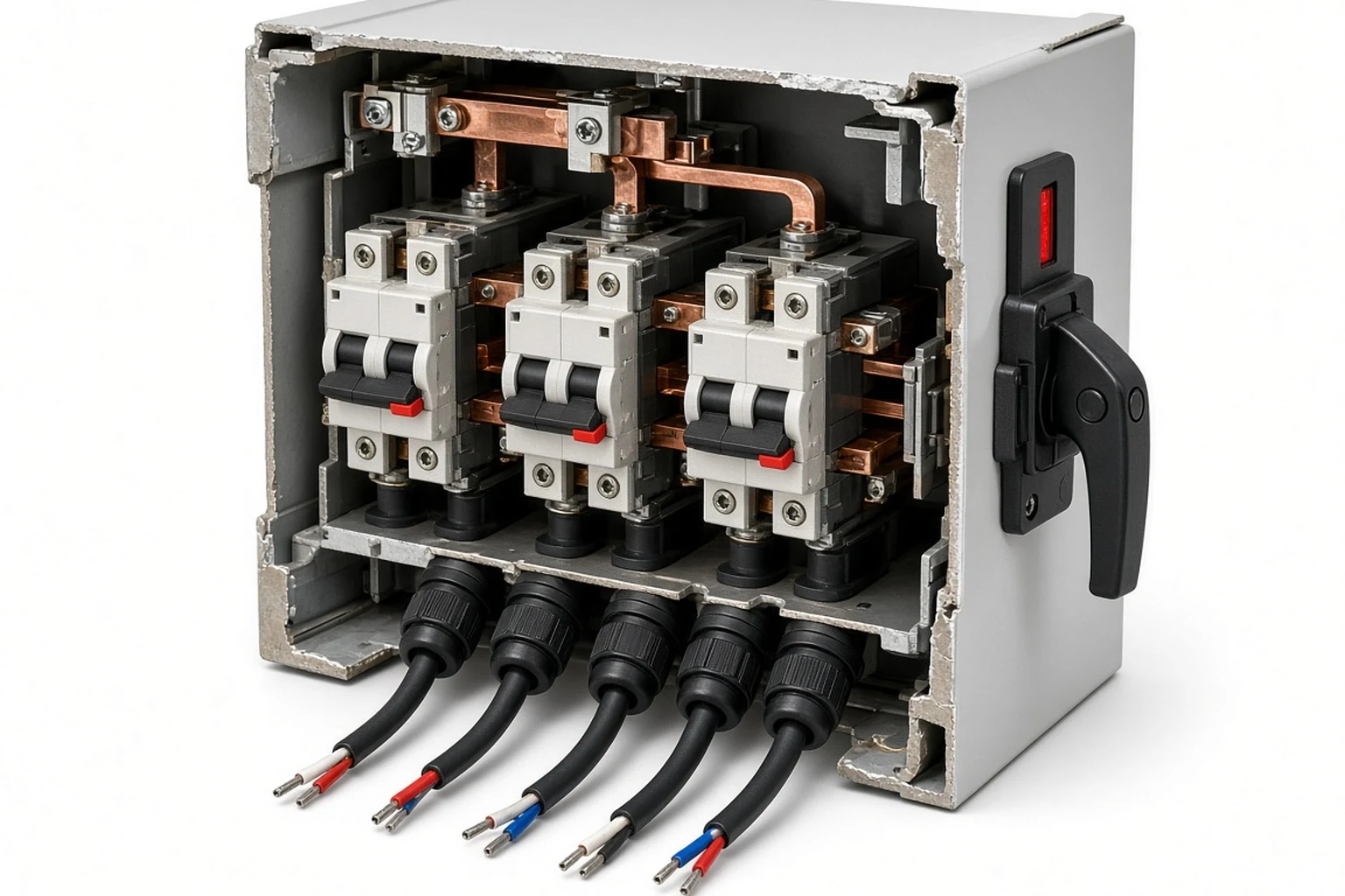
Cutaway view of an overhead busway tap-off unit illustrating the external rotary handle interlock, internal multi-pole switching and protection assembly, and bottom drop-whip cable glands.
Overhead plug-in tap-off units provide the upstream branch or feeder protection for the drop whip and the rack PDU input. Under Starline Track Busway 1000T5 Clauses 6.3.1 through 6.3.5, plug-in units shall be polarized to avoid incorrect installation, can be added, removed or repositioned without de-energizing the busway, shall use either a circuit breaker or a fuse for branch circuit protection, and shall have a soldered wire connection on each stab directly connected to the line side of the circuit breaker (use of crimp connectors is prohibited). Under Starline Track Busway 1000T5 Clause 6.3.11 and Clause 6.3.12, plug-in units shall have the ability to provide up to a 400 amp load in certain plug-in unit configurations and shall have a minimum of 10kAIC and the ability to obtain a maximum of 200kAIC. At the workplace regulatory level, under OSHA 1910.304(f)(1)(iv), overcurrent devices shall be readily accessible to each employee or authorized building management personnel and may not be located where exposed to physical damage. In addition, under OSHA 1910.304(b)(4)(ii)(C), where connected to a branch circuit supplying two or more receptacles or outlets, receptacle ratings shall conform to Table S-5, or where larger than 50 amperes, the receptacle rating may not be less than the branch-circuit rating.
Between the upstream tap-off box and the vertical rack PDU, manufacturer installation manuals specify exact upstream breaker pairings and continuous load derating rules. On Emerson Vertiv Liebert MPH2 Rack PDUs in Section 2.3.6, a field-provided external circuit breaker must be installed upstream of the MPH2 Rack PDU, must be sized according to the input rating of the PDU (Table 2-4), and serves as the primary input power disconnect for the MPH2. In Emerson Vertiv Liebert MPH2 Table 2-4 (Upstream circuit breaker rating), for North American (NA) models the rated current of the upstream circuit breaker is 15 A for 12 A maximum input current per pole, 20 A for 16 A, 30 A for 24 A, 50 A for 40 A, and 60 A for 48 A, while for EU/WW models it is 16 A for 16 A, 32 A for 32 A, and 63 A for 63 A. Furthermore, on Emerson Vertiv Liebert MPH2 Rack PDUs in Section 5.0, per UL 60950-1 2nd Ed ITE safety-standard requirements, the current ratings of UL Listed models are 80% of input-plug, branch-circuit-breaker, and receptacle maximum current ratings.
| Rack PDU Breaker Architecture | Verified Branch Protection and Receptacle Specification |
|---|---|
| Universal PDU breaker count tiers | On the Vertiv Geist Universal PDU (UPDU) handout SL-70676, model VP7UU001 is a 3-breaker vertical switched UPDU rated up to 11kW (16A 3~ WYE 230/415V max, 24A 3~ Delta 208V max, 48A 1~ 240V max) with (24) Combination Outlet C13/C19, whereas model VP7UV002 is a 6-breaker vertical switched UPDU rated up to 22kW (32A 3~WYE 230/415V max, 48A 3~ Delta 208V max, 63A 1~ 240V max) with (24) Combination Outlet C13/C19. |
| Facility cable capacity cap by breaker count | On the Vertiv Geist Facility Side Cable (FSC) chart SL-70676, FSC3U001 (16/20A, 3P+N+E IP44, 230/400V WYE) supports 11.0kW on both 3 Breaker and 6 Breaker UPDUs, FSC1N001 (L6-30P, 30A, 208V) supports 4.9kW on both, and FSC3N003 (L21-30P, 30A, 120/208V WYE) supports 8.6kW on both, whereas FSC3U002 (30/32A, 3P+N+E IP44, 230/400V WYE) supports 11.0kW on a 3 Breaker UPDU vs 22.0kW on a 6 Breaker UPDU because max kW on the 3-breaker unit is limited by internal UPDU circuit breakers, and FSC3N006 (60A, 3P+E IP44, 208V Delta) supports 9.9kW on a 3 Breaker UPDU vs 17.2kW on a 6 Breaker UPDU. |
| Six-branch switched PDU protection | On the Server Technology PRO2 Switched C2W48CE-YQME2M66 Rack PDU, the input is a 208V Wye 60A IEC 60309 3P+N+G 9Hr plug with 60A input current, 48A rated input current, and 17.3 kW input power capacity, feeding (36) IEC 60320/C13 outlets (≤ 12A @208V L-L, 15A Peak) and (12) IEC 60320/C19 outlets (≤ 16A @208V L-L, 20A Peak), protected by six UL 489, CSA C22.2 No. 5 & IEC/EN 60947-2 compliant 2-pole, 20A trip circuit breakers (rating ≤ 16A, 10 kAIC interrupt rating). |
| Single-phase hydraulic-magnetic input and outlets | On the Legrand Linkeo 0U Basic Rack PDU FT-646966-EN-02, the input is an IEC 60309 32A 2P+E plug on a 3m (9.84 ft) HO7RNF 3G6 cable (32A maximum input current, 230V single-phase, 7.4kW at 230V) feeding 20 C13 + 4 C19 outlets with 100 N cord retention and Magnetic Hydraulic (curve D) circuit breakers. |
| Temperature-stable MCB breaking capacity | On the Legrand Linkeo 0U Basic Rack PDU FT-646966-EN-02, the magnetic-hydraulic MCB is not affected by ambient temperature increase, is rated 16A at 250 V (50/60 Hz) with 1 pole as standard and 2 poles as a CTO option, and has a breaking capacity (Icn) of 3000. |
Size high-density AI rack feeds, ambient derating, and redundancy tests
The fourth check sizes the combined busway tap-off and rack PDU architecture for high rack power density, diversity factor rules, ambient temperature derating, and dual-busway A+B fail-over. In the ABB High-Density Tap-off Unit Reference Design, typical power densities of IT racks in AI server data centers are 35kW, 60kW, 70kW, 100kW, 150kW and 200kW. When sizing the tap-off unit for these high-density cabinets, published reference guidelines require full load dimensioning without diversity reduction on single-circuit tap-offs. According to ABB's summary of IEC 61439-6, the rated current of a tap-off unit (Inc) shall be equal to or higher than its assumed load for specified mounting conditions (horizontal or vertical, below or on top of the busduct), and the rated diversity factor (RDF) is equal to 1 for a tap-off with one outgoing circuit. In the ABB High-Density Tap-off Unit Reference Design, for data centers, power distribution to an IT rack shall be dimensioned for total installed power with rated diversity factor (RDF) equal to 1.
Ambient temperature derating must also be evaluated across both the overhead busway elevation and the tap-off box breaker compartment. In the ABB High-Density Tap-off Unit Reference Design, while the ASHRAE recommended temperature range for white space rooms is 18°C to 27°C (allowed range 10°C to 35°C), busduct systems are typically designed for ambient temperatures of 35°C to 40°C and never higher than 55°C, and protection devices can be dimensioned for an ambient temperature of 55°C per IEC 61439-2. In the ABB High-Density Tap-off Unit Reference Design, MCCBs and MCBs provided with thermo-magnetic trip units have the thermal threshold for overload protection set at 40°C, so for ambient temperatures different from the set one it is necessary to consider a shift of thermal trip thresholds. In the ABB High-Density Tap-off Unit Reference Design, in most cases ABB Tmax XT MCCBs do not require any performance derating up to 55°C.
For overhead track busways, on the Starline Track Busway 1000T5 Metric System in Clause 3.2.1, the busway shall operate with continuous load with no derating up to 55 degrees Celsius, 0.95 at 60 degrees Celsius, 0.925 at 65 degrees Celsius, and 0.9 at 70 degrees Celsius, at 0 to 95 percent noncondensing relative humidity and altitudes from sea level to 2000m (6600 feet).
Finally, verify dual-busway A+B capacity and live fail-over before energizing multi-PSU GPU servers, and align cabinet cord routing with our redundant power supply A/B feed mapping guide. In the Siemens XJ-L HD Busway white paper, each tap contains a circuit breaker which protects the busway from a branch-level overload under normal conditions, and in a fully redundant A-B system each busway path must be designed to carry the entire load of dual-fed cabinets. In NVIDIA's DGX SuperPOD Data Center Design for DGX H100, the preferred power for high-density deployment patterns is 415 VAC, 32A, three-phase, N+1, and power supplied to each rPDU must originate from separate data center floor-mounted or busway PDUs, with four of the six internal power supplies energized for each DGX H100 system to operate. In NVIDIA's DGX SuperPOD Data Center Design for DGX H100 (Planning and Deploying Power Connections), facilities personnel must label all power connections to indicate the source of power (PDU #) and specific circuit breaker numbers used within each PDU, color-code the power cables and associated rPDUs, and perform an AC verification test by turning off individual circuit breakers feeding each rack power strip to verify redundancy.
Prepare your busway tap-off and rack PDU specification for an RFQ
Before releasing a procurement package for overhead tap-off whips and vertical rack power units, consolidate these specification parameters so the quoted hardware matches both your overhead busway track and your cabinet rear rail layout:
- Overhead busway track and tap-off unit parameters: Specify the busway manufacturer family, track ampacity, pole and neutral bar configuration, tap-off box breaker pole count, straight or slash voltage rating, and trip curve.
- Drop whip cable and locking connector schedule: Define whether the tap-off box uses a hardwired drop whip or an enclosure-mounted receptacle, along with the whip jacket type, conductor cross-section, routed drop length into the cabinet top or floor, and locking plug pin configuration.
- Rack PDU input entry and branch breaker layout: State top-entry or bottom-entry whip orientation, total continuous kilowatt target per cabinet, hydraulic-magnetic branch circuit breaker count, and receptacle count per bank.
- Redundant feed pairing and cord labeling: Document how Feed A and Feed B tap-off boxes map to left and right vertical rack rails, and specify pre-labeled jumper cord colors for each power supply bank.
We quote vertical rack power distribution units, overhead tap-off input whips, and matched jumper cord bundles with complete assembly specifications and pre-shipment inspection records. Submit your completed parameters through our PDU RFQ specification checklist or bundle pre-matched vertical rack power units, locking jumper cords, and retention clips through the AI rack power kit.
Sources
- U.S. Occupational Safety and Health Administration — Wiring Design and Protection Rules
- U.S. Occupational Safety and Health Administration — Wiring Methods, Components, and Equipment for General Use Rules
- UL Solutions — Safety Requirements for Busways and Associated Fittings
- UL Solutions — Low-Voltage Switchgear and Controlgear Assemblies for Busbar Trunking Systems
- ABB — High-Density Data Center Overhead Busway Tap-Off Reference Guide
- Starline — Track Busway Installation, Operation, and Maintenance Manual
- Vertiv — PowerBar Overhead Data Center Busway Technical Brochure
- Vertiv — PowerBar High-Power Busbar Trunking System Brochure
- Siemens — Sentron Data Center Busway Application Overview
- Vertiv — Liebert Rack Power Distribution Unit Installer and User Manual
- Vertiv — Geist Rack Power Distribution Unit Family Specification Guide
- Server Technology — Switched Vertical Rack Power Distribution Unit Specification Sheet
- Legrand — High-Density Vertical Rack Power Distribution Unit Technical Data Sheet
- NVIDIA — SuperPOD Data Center Electrical Design Guide